Vypyr VIP 2 - schematics, or photos of tear down?

A forum for discussing the Vypyr series amplifiers, Sanpera footswitches and share settings
Post Reply
BiscuitP1mp
New Member
Posts: 5
Joined: Thu Jul 28, 2016 1:17 am

Vypyr VIP 2 - schematics, or photos of tear down?

Post by BiscuitP1mp » Wed Aug 31, 2016 6:27 pm

Hey everyone.

I want to pull my amp apart and give it a clean. Basically it just needs a good dusting.

I know it's entirely complicated to pull small amps like this apart, but very keen to have some references before I start tearing it apart. I've done some research but can't find anything specific for the Vypyr VIP 2.

I found the below image which gives me some clues to where it's screwed in. Can I just take the top off the amp without taking board out and disconnect from speaker?

Image

My biggest concern is how the board is connect to rest of amp? I know I need to be careful with wire connections to speaker. Need to avoid disconnecting, I don't have a soldering kit/desoldering bench at the moment.

Thank you!

User avatar
Enzo
Member
Posts: 9535
Joined: Fri Sep 12, 2008 10:24 pm
Location: Lansing, Michigan

Re: Vypyr VIP 2 - schematics, or photos of tear down?

Post by Enzo » Wed Aug 31, 2016 8:37 pm

Honest, it doesn't need cleaning unless you leave it in a VERY dirty environment.

But to answer your questions, that photo tells the tale. There are four screws down through the top of the wood cabinet to hold the chassis in place. Usually chassis slides out the rear, but the photo appears like the trim strip will want it to slide out the front. Once the four screws are out, it should become obvious which way the chassis comes out. Be aware, a lot of times when an amp is made, there is a certain stickiness to the innards, and the chassis might initially stick to the paint or tolex. There are no hidden screws, but the chassis might seems stuck at first.

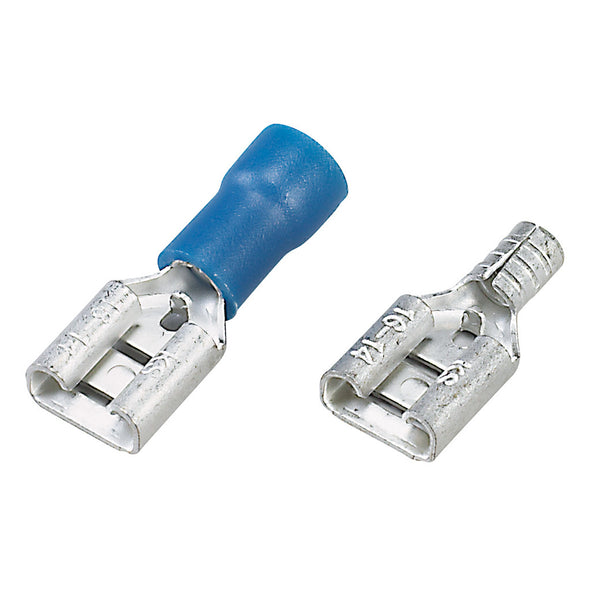
Yes, you will have to pull the wires off the speaker for it to come all the way out. They are the yellow and blue ones. Yellow to the + terminal on the speaker. The wires are not really soldered to the speaker are they? Some are soldered, but most are push-on connectors like these:

Image

You do have to be careful as they can hold pretty tight, and they can let go all of a sudden when you pull hard, and you whack your knuckles.

The interior photo looks typical. And there is absolutely no reason you need to dismount those circuit boards. if you want to clean something, put your vacuum cleaner on blow and blow anything loose out of the chassis. Then STOP.

Look rear center, see the white goo oozing out from behind the couple transistors, and note the transistors are screwed to a heavy metal slab and there is a little white goo hiding behind that. the goo is thermal silicone paste, and if you dismount the things there, you will have to replace the goo. it is important to the amp cooling itself.

I can't tell from the picture, but see the flat gray ribbon cables connecting boards together? The connectors on the ends of the ribbons are many times held down with a dab of glue. Also it is VERY important that the ends of those ribbons go onto the connector pins correctly. There are two little parallel rows of pins sticking up from the board. it is easy to get the connector off one row or down one pin either direction, and then circuits blow. You need to know what you are doing. As an authorized service tech, I rarely have top pull a board unless I am replacing a part on it.

All the panel controls with lights around them? Those are really rotary selector switches called encoders, they are not like common volume and tone controls. This amp is really a computer inside.

The schematic is available from customer service at Peavey, but it only shows the circuit diagram and the board parts placement. there is no picture of the chassis or cabinet.


If your amp is working well, I highly recommend leaving the insides alone. Something I teach my trainee techs:

When the amp works, stop fixing it.

User avatar
gcolbert
Member
Posts: 171
Joined: Sun Feb 22, 2009 12:52 pm
Location: Maryland, USA
Contact:

Re: Vypyr VIP 2 - schematics, or photos of tear down?

Post by gcolbert » Sat Sep 03, 2016 10:59 am

There isn't anything inside the chassis that needs to be cleaned. Just wipe down the outside and let things be.

Glen

BiscuitP1mp
New Member
Posts: 5
Joined: Thu Jul 28, 2016 1:17 am

Re: Vypyr VIP 2 - schematics, or photos of tear down?

Post by BiscuitP1mp » Sat Sep 03, 2016 8:45 pm

Thank you Enzo, and Glen.

I need to pull my amp apart to get at rear of pots. I have a wonky Low pot that when I clean from front, starts working for a while, then fails after a while. When it's playing up, counter-clockwise turns result in dial changing in a clockwise direction. Getting some contact spray down behind the stem bit the knob sits on get's it working, albeit temporarily.

It was recommended by another owner of the same model amp, to try and get some contact spray in behind pots, as I may just have some build up that's affecting the optical steppers (hope I got that language correct). There place I live in is a dust bowl. I'm just about sweeping and wiping down my most surfaces every other day.

Thanks again.

lostsquadron
New Member
Posts: 7
Joined: Sat Sep 03, 2016 2:23 pm

Re: Vypyr VIP 2 - schematics, or photos of tear down?

Post by lostsquadron » Sat Sep 03, 2016 9:18 pm

Its all in the top except for the speaker connection. Once you take the back off and four top screws out, there are also 4 that you have to take off from inside above the speaker that screw into the back of the plastic trim. Whole thing slides out the front after that.

BiscuitP1mp
New Member
Posts: 5
Joined: Thu Jul 28, 2016 1:17 am

Re: Vypyr VIP 2 - schematics, or photos of tear down?

Post by BiscuitP1mp » Sun Sep 04, 2016 4:25 pm

Thanks Lostsquadron

Post Reply